Fire Tube Boiler Design Calculation
Fire tube steam boilers are designed for the purpose of industrial scale heat exchange in order to heat saturated liquid entering the control volume to a saturated gas. Exiting gas leaving the control volume may experience a pressure drop when returning to atmospheric pressure. Three pass fire tube steam boilers are composed of a cylindrical hull filled with thermal insulation in which a series of tubes are contained. Hot air from a burner is passed from a furnace in the 1st pass to a series of tubes in the 2nd pass, then to a series of tubes in the 3rd pass. Finally, the hot air exits through a chimney. The boiler is filled with water up to the top level of the 3rd pass pumped from the base of the boiler.
Steam is then pumped from the top of the boiler to wherever heating is needed. The boiler contains a safety valve that, when the pressure becomes too high due to blockage or overheating, releases the excess steam.
Take a threepass fire tube steam boiler with a capacity of 5000 kg of steam per hour and a operating pressure of 10 bar for example. The Figure below equations shows a standard three pass fire tube steam boiler system used as a template for our engineering team’s design.
Conduction through piping to the water is described in the equation
Q = A[(Tair − Tw)/(1/hair + ttube/Ktube + 1/hw)]
where:
Q = Heat transfer rate in KW
Tair = Temperature of the air in K
Tw = Temperature of the water in K
hair = Thermal conductivity of air in KW/m2*K
ttube = Thickness of tubes
Ktube = Thermal conductivity of carbon steel in KW/m2*K
hw = Thermal conductivity of water in KW/m2*K
Total heat transfer produced by furnace is modeled by the equation
Q = (h3 − h2)
where:
Q = Heat transfer rate in KW
= Mass flow rate in kg/s
h2 = Water entering boiler at 10 bar and 20
oC
h3 = Enthalpy of Steam exiting boiler at 180
oC
Power of the pump is modeled by the equation
Q = v(P2 − P1)
where:
Q = Power required by pump in KW
= Mass flow rate in kg/s
v = Specific volume of water entering pump (assumed incompressible) in m3
/kg
P2 = Pressure exiting pump in Kpa
P1 = Pressure entering pump in KPa
- >>Previous: How To Select Boiler Capacity
- >>Next: Steam Boiler Capacity Calculation
Hot Product
-
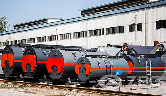
WNS Fire Tube Boiler
-
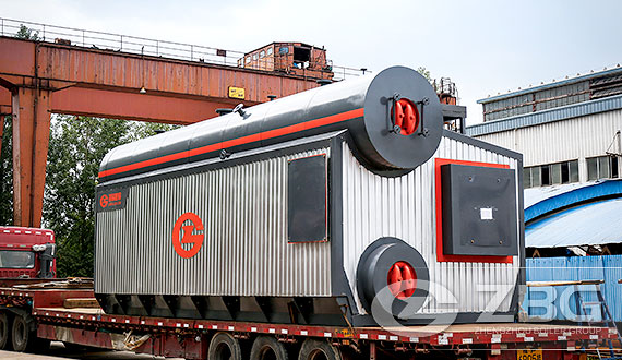
SZS Series Oil And Gas Fired Boiler
-
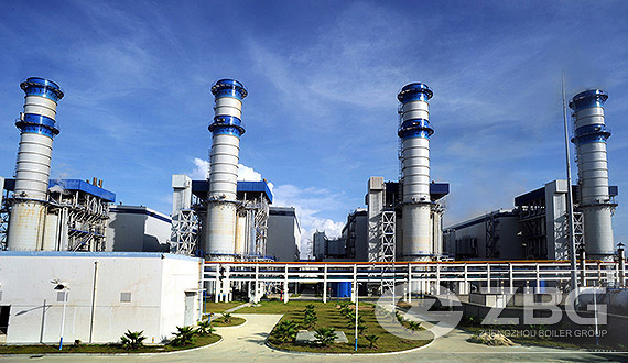
Gas / Oil Fired Power Plant Boiler