What Are the Auxiliary Equipment of Steam Boilers?
2022-12-08 09:08:062.1.5. Burner unit
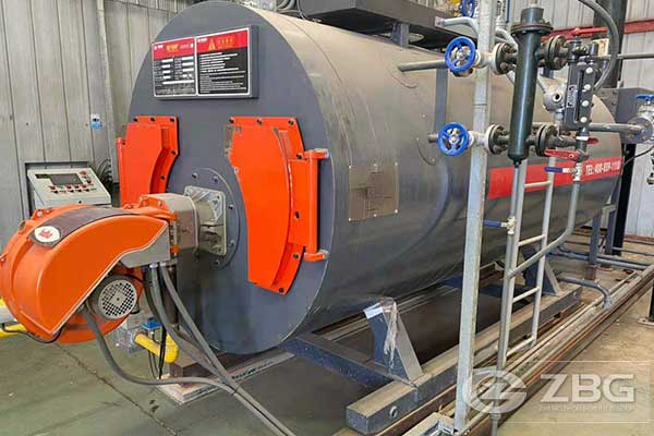
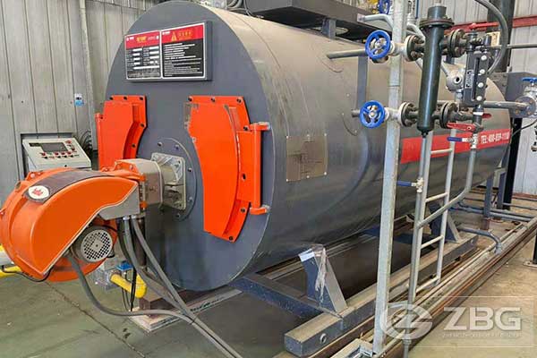
i. Provide forced-draft automatic FO burner integral with front head of boiler designed to burn fuel oil.
ii. All combustion air shall be furnished by the burner blower, which shall be an integral part of the burner.
iii. Blower: Statically and dynamically balanced to supply combustion air. Equipment with inlet silencer and outlet air dampers. Direct connect to motor.
iv. Oil Pump: Capacity approximately twice maximum burning rate.
v. Oil Burner Piping: Include oil pressure regulating devices, oil metering controls, solenoid shut off valves, oil strainer and instrumentation, all integrally mounted on unit and adequate to permit system adjustment for optimum performance.
vi. Drip Pan: Provide on floor under each oil burner 600 x 600 x 50 mm deep, 1.6 mm thick galvanized steel soldered pan.
vii. Provide a permanent observation port in the burner to allow observation of both the pilot and the main flame.
2.1.6. Terminal Box
i. Integrated terminal box that is already wired.
ii. Pre-assembled, plug-in and coded cable bundles to simplify the
electrical wiring between the boiler control cabinet and the terminal box.
2.1.7. Control Cabinet.
i. The boiler control panel shall be mounted on the wall adjacent to the boiler. Independent mounting is required to avoid vibrations that may be generated by the boiler. Panel shall have provisions to padlock controls in the OFF position to protect service personnel.
ii. The control cabinet shall contain the flame-monitor and programming control, a magnetic motor starter with thermal overloads for the fan, a step-down transformer (if necessary) to provide power for all of the control components, a burner ON-OFF switch, control-circuit breaker, numbered terminal strips, color-coded wiring, engraved nameplates, reset push button, and necessary relays and switches.
iii. Panel shall include indicating lights to show operating conditions of low water level, flame failure, fuel valve open and load demand. Mount indicating lights and switches in hinged drop panel for wiring to access.
iv. Provide interface hardware to allow remote access for monitoring and controlling the boiler.
2.1.8. Alarm System
i. Provide an alarm system with the alarm panel incorporated in the boiler-control panel.
ii. All wiring in the alarm panel and on the controls external to the panel shall be factory installed and tested, except for interconnecting wiring between the packaged boiler unit and a remotely-mounted alarm panel.
iii. The first off-limit conditions shall be incorporated in the ‘first-out’ alarm panel:
a) Flame failure (manual reset on flame-monitor controller)
b) Low water level (automatic reset when low water condition is corrected)
c) High water (automatic reset) for steam
d) High pressure (manual reset on high-steam-pressure controller) for steam
e) Automatic safety shutoff valve not closed prior to start-up
f) Low-low water (manual reset on water level control)
g) Low combustion airflow
iv. Provide alarm lights on the alarm panel to indicate each off-limit condition, an audible alarm on the panel, and an alarm test circuit.
v. Design the alarm system to send one alarm signal to the Central Control Room
2.2.Feed water supply unit:
2.2.1. Feed Pump Unit
i. Vertical multi-stage high-pressures centrifugal pumps with a fully enclosed, fan-cooled motor.
ii. pressure indicator,
iii. shut-off, filter and non-return valves
2.2.2. Water Softening Unit
i. Fully automatic raw water softening system comprising of Water softening system and a salt-softening receptacle.
ii. Capacity of at least 5.0 m3/hr
iii. Double aggregate with flow-dependent control, consisting of:
a. 2 exchanger tanks including the nozzle system
b. 2 fillings of ion exchanger material
c. 1 control head inclusive of cover for fully automatic regeneration with electric control unit, incl. operation switches, display, incl. power connection cable and plug with earth contact.
d. 1 salt tank with cover and integrated brine system
e. 1 contact water meter
f. 1 fine filter with initial filter insert, control via removable glass cover.
g. 1 system isolator incl. screw joint and packings, acc. to DIN 1988
2.2.3. Water Storage and Chemical Dosage
i. Feed in and storage of condensate and make up water
ii. Steam heated feed water tank of 10000 lts capacity
iii. Condensate Return Skid with a Condensate tank (90% condensate Recovery), duty and standby Condensate return pumps.
iv. The chemical dosing system
v. Water drainage connection, sampling device, pressure indicator, control fittings, shut-off and filter valves and other associated fittings.
2.3.Blow-down, expansion and cooling
i. Provide connections to the existing blowdown system at KPRL
2.4.Oil supply Unit
i. Double stations pump design to provide 100% redundancy and enable filer cleaning without interruption of operations
ii. Pumping and filtering HFO for supply to burner
iii. Oil Flow meter
2.5.Steel Chimney
i. Free-standing, double-wall and self-supporting construction in accordance with EN 1993-3-2
ii. At least 15M High and 600 mm Diameter.
iii. Special chimney paint, light grey (RAL 7035) or equivalent
2.6.Steam distributor/Manifold
i. A 10” collecting pipe with 5pcs 3” pipe outlets fully assembled with flange connections and all necessary fittings
ii. distributors fitted with pressure indicators, shut-off, non-return and condensate drain valves
2.7.General Features
i. Provide pre-assembled modules and a pre-parameterised boiler control system for easy installation and commissioning
ii. Easy wiring on site thanks to plug-in connections
iii. Easy to maintain – simple to inspect on both the flue gas side as well as the water side
iv. Intuitive boiler control on PLC basis with very high transparency of operating data
v. Automatic start-up, standby and shutdown control
3. EXECUTION
3.1. Installation
i. Critical boiler installation dimensions and considerations shall be incorporated into and supplied by the manufacturer on equipment general arrangement drawings.
ii. The boiler shall be installed on a concrete base. The Complete structural, mechanical, and electrical connections in accordance with manufacturer's installation instructions. KPRL shall provide the location, concrete base, terminal points for power and steam connections.
iii. Steam, fuel, and other connections: The location, size, and specifications for each applicable connection will be provided by the manufacturer’s supplied boiler Piping & Instrument Diagram, boiler general arrangement drawing, and bills of material.
iv. Electrical connection and service requirements shall be provided and clearly designated in the manufacturer’s electrical wiring diagrams.
v. Provide and erect a stack or duct for the boiler (chimney)
3.2.Commissioning and Operation
i. The contractor/Boiler manufacturer shall ensure that all utilities,
connections, piping, electrical, and other associated equipment and tieins are completed, serviceable, and ready for boiler operation.
ii. The boiler manufacturer will make available the services of a factory authorized service engineer for the boiler start-up.
iii. A comprehensive start-up report shall be completed and provided to the client and other parties. iv. Factory authorized training for operators, maintenance, and others shall be performed before or at the time of commissioning.
v. The client shall provide operators for the operation of the boiler. The contractor, however, must provide technical support for safe and efficient operation of the boiler after commissioning. Such support may be through emails, telephones remote online support and site visit when required.
3.3.General Remarks:
i. The manufacturer is responsible for ensuring that the equipment is designed and constructed in accordance with the specifications and codes referred to on the requisition and/or drawings.
ii. The manufacturer is responsible for ensuring that the design, including thicknesses of pressure parts, is satisfactory for the design conditions indicated on the requisition and/or drawings.
iii. Calculations and thicknesses of material supplied to the manufacturer are for information and tendering purposes only. The manufacturer shall make his own calculations for which he is fully responsible. The manufacturer shall ensure that the equipment supplied conforms to all applicable codes and national statutory regulations, and he shall obtain all necessary approvals from statutory authorities.
4. SUBMITTALS
4.1. Shop Drawings:
Dimensioned and detailed drawings, including control wiring diagrams complete and specific for the boiler supplied. Indicate the following information:
i. General arrangement showing terminal points, instrumentation test connections.
ii. Clearances for operation, maintenance, servicing, tube cleaning, tube replacement.
iii. Foundations with loadings, anchor bolt arrangements.
iv. Piping hook-ups.
v. Equipment electrical drawings.
vi. Burners and controls.
vii. All miscellaneous equipment.
viii. Flame safety control system.
ix. Breeching and stack configuration.
4.2.Product Data: Manufacturer’s technical data shall be presented in an organized and bound submittal and shall include the following:
4.2.1. Boiler: i. Product General Arrangement Drawing. ii. Copies of manufacturer’s product literature, specifications and datasheets. iii. Product dimensions including required clearances. iv. Unit weights (shipping and operating). v. Manufacturers detailed report, material certificates, welding details, NDT reports, final testing reports including hydrostatic report, final acceptance and warranty report.
4.2.2. Boiler Controls, Trim, & Instrumentation:
i. Piping & Instrument Diagrams.
ii. Instrument & Electrical symbols legends.
iii. Drawing Index.
iv. Bills of Materials listing manufacturer, models, and quantity of supplied components.
v. Control Panel Layout Drawings.
vi. Panel Controls and Indicators Layout Drawing.
vii. Ladder Diagram type wiring schematics.
viii. Wiring schematic drawing index and symbols legend.
4.2.3. Accessories and Custom Components:
i. General arrangement or component drawing.
ii. Component Data Sheet.
iii. Panel layout drawing (when applicable).
iv. Wiring Diagram (when applicable).
Instrumentation symbols and identification on process engineering flow schemes DEP 32.10.03.10-Gen.
Control system and instrumented protective functionsfor fired equipment - System for a single-burner furnace(S 24.024 and S 24.026)DEP 32.24.20.30-Gen.
Instrumentation for equipment packages DEP 32.31.09.31-Gen.
Steel stacks (amendments/supplements to CICINDModel Code)DEP 34.24.26.31-Gen.
Steel structures DEP 34.28.00.31-Gen.
Relief devices – Selection, sizing and specification DEP 80.36.00.30-Gen.
For all inquiries, please fill in the form below (* are required) to send us a brief message, and we will get back to you as soon as possible.
