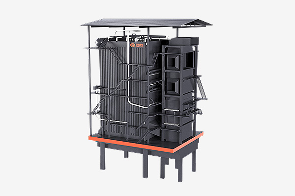
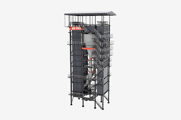
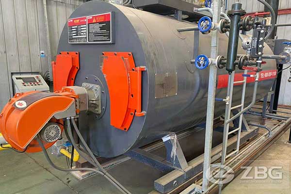
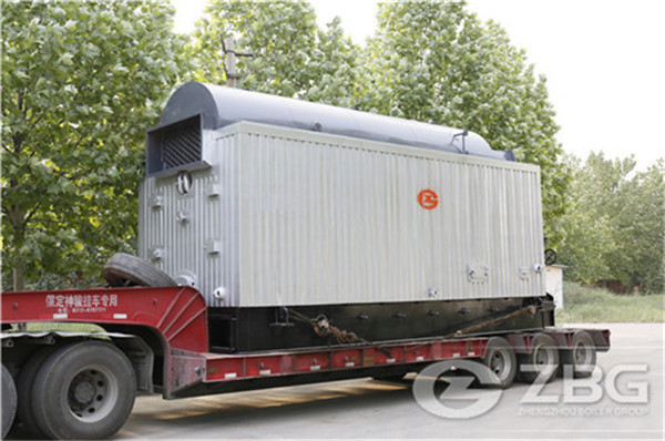
10MW Biomass Power Plant 50T/H Biomass Steam Boiler
2022-12-02 12:01:4610MW Biomass Power Plant 50T/H Biomass Steam Boiler
|
SN |
Description |
Unit |
Value |
|
A |
Steam Generator (Boiler) |
|
|
|
1 |
Type |
- |
|
|
2 |
Nos. of Unit |
Nos. |
1 |
|
3 |
Capacity |
TPH |
50 |
|
4 |
Main Steam Pressure |
Kg/cm2(a) |
45 |
|
5 |
Main Steam Temperature |
oC |
420 ± 5 |
|
6 |
Main Steam Temperature Control Range |
%MCR |
60 to 100 |
|
7 |
Startup Vent Capacity |
%MCR |
30 |
|
8 |
Feed Water Temperature to Economizer inlet |
oC |
130 |
|
9 |
Feed Water Temperature at Deacrator outlet |
oC |
130 |
|
10 |
Performance Guarante Fuel |
- |
100% Palm Waste |
|
11 |
Secondary Fuel |
- |
NA |
|
|
|
|
|
|
B |
FD Fans |
|
|
|
1 |
Nos. per unit |
%MCR |
2 x 60% |
|
2 |
Air Control Through |
- |
VFD & Pneumatically operated Inlet Multi-lower Damper |
|
3 |
Type of Lubrication |
- |
Grease |
|
|
|
|
|
|
C |
SA Fans |
|
|
|
1 |
Nos. per unit |
%MCR |
2 x 60% |
|
2 |
Air Control Through |
- |
VFD & IGV |
|
3 |
Type of Lubrication |
- |
Grease |
|
|
|
|
|
|
D |
ID Fans |
|
|
|
1 |
Nos. per unit |
%MCR |
2 x 60% |
|
2 |
Air Control Through |
- |
VFD & Pneumatically Operated inlet Multi-louver Damper |
|
3 |
Type of Lubrication |
- |
Grease |
|
|
|
|
|
|
E |
Boiler Feed Pumps |
|
|
|
1 |
No. of Units |
Nos. |
2 x 100%(1W + 1S) |
|
2 |
Type of pump and drive |
- |
Multistage horizontal sentrifugal pumps, electrically driven with VPD for all pumps |
|
3 |
Suction Side Isolation valve |
- |
Manual Gate |
|
4 |
Discharge Side Isolation valve |
- |
Motorized Gate |
|
5 |
Minimum Re-circulation Arrangement |
- |
ARC valve |
|
6 |
Type of Lubrication |
- |
Grease |
|
7 |
Mechanical seal provided |
- |
Yes |
|
8 |
Nois Level at 1m limited to |
db(a) |
90 |
|
|
|
|
|
|
F |
Deserator |
|
|
|
1 |
Type of Deserator |
- |
Spray Cum Tray Type |
|
2 |
Nos. of Deserator |
Nos. |
One |
|
3 |
Deserator feed water storage between normal working level to low-low level |
Min |
20 |
|
4 |
Deserator pressure control |
- |
Variable Pressure |
|
5 |
Dissolved oxygen at deserator outlet |
ppm |
0.005 |
|
|
|
|
|
|
G |
Air Pre-Heater |
|
|
|
1 |
APH Type |
- |
Tubular, non-recuperative |
|
|
|
|
|
|
H |
ESP |
|
|
|
1 |
Nos. of ESP per Unit |
Nos. |
1 x 100% |
|
2 |
Nos. of Flue gas path of ESP |
Nos. |
1 x 100% |
|
3 |
ESP Emission level with all fields in service |
Mg/Nm3 |
< 100 |
|
4 |
ESP hopper capacity |
Hrs |
4 |
|
5 |
Elevation of hopper flange from FFL |
M |
2.5 |
|
6 |
Type of Level switch in hopper |
- |
RF type |
|
7 |
Thickness of MS Plate for ESP construction |
Mm |
5 |
|
8 |
Type of Insulation Material |
- |
LRB mattress |
|
9 |
Type of cladding Material |
- |
22 / 24 SWG Plain Aluminium |
|
10 |
Construction of ESP Supporting structure |
|
Concrete + steel |
|
|
|
|
|
|
I |
Start up Fuel |
- |
Diesel / Charcoal assisted |
|
|
|
|
|
|
J |
Fuel Busker and Fuel Feeding System |
|
|
|
1 |
Nos. of fuel Bunkers per unit |
Nos. |
NA |
|
2 |
Capacity of fuel bunker |
Tons |
NA |
|
3 |
Type of fuel feeding |
|
Four nos. screw feeders (with VFD) with feeding hopper and continuous feeding conveyor (carrier) |
|
|
|
|
|
|
K |
Duct |
|
|
|
1 |
Fuel Gas duct thickness |
mm |
5 |
|
2 |
Air side duct thickness |
mm |
4 |
|
|
|
|
|
|
L |
Structural |
|
|
|
1 |
Construction up to BoilerOperating floor |
- |
MS Structural |
|
2 |
Extent of Roof & Side Cladding |
- |
Up to steam drum level |
|
3 |
Material of Side Cladding |
- |
GI Sheets (Multicolor) |
|
|
|
|
|
|
M |
Safety & Relief Valves |
|
|
|
1 |
Total Nos. of Safety Valves |
- |
Three (2 on Boiler Drum and 1 on Superheater) |
|
2 |
Type of Safety Valve |
- |
Spring Loaded Mechanical |
|
3 |
Silencer provided for |
- |
SH safety valve & startup vent valve |
|
4 |
Noise limited by silencer |
db(s) |
11- at 10m |
|
|
|
|
|
|
N |
Steam Turbine |
|
|
|
1 |
Nos. of unit |
Nos. |
1 |
|
2 |
Nominally rated capacity – gross |
MW |
10.0 |
|
3 |
Inlet steam pressure |
Kg/cm2(a) |
42 |
|
4 |
Inlet steam temperature |
0C |
410 |
|
5 |
Exhaust steam pressure |
Kg/cm2(a) |
0.10(normal) |
|
6 |
Deaerator per turbine |
Nos. |
One |
|
7 |
Noise level at 1 m limited to |
dB(a) |
90 |
|
|
|
|
|
|
O |
Water System |
|
|
|
1 |
Nos. of raw water transfer pumps |
Nos. |
2 nos (1W + 1S) |
|
2 |
Type of raw water transfer pumps |
- |
Horizontal Centrifugal |
|
3 |
Location of raw water transfer pumps |
- |
Tank base |
|
4 |
Chlorination system for raw water |
- |
Provided |
|
5 |
Design Margin on Cooling water system |
% |
10 |
|
6 |
Type of cooling water |
- |
Counter flow |
|
7 |
Nos. of streams of clarifier and primary filters |
Nos. |
1 |
|
8 |
Capacity of each stream of primary treatment system |
m3/hr |
25 |
|
9 |
Nos. of stream in UF + RO + Degasser + MB Plant |
Nos. |
1 |
|
10 |
Capacity of each stream of UF +RO + Degasser + MB |
m3/hr |
15 at output |
|
11 |
Hours of Operation |
hrs |
20 |
|
12 |
Output between regenerations |
m3 |
300 |
For all inquiries, please fill in the form below (* are required) to send us a brief message, and we will get back to you as soon as possible.
