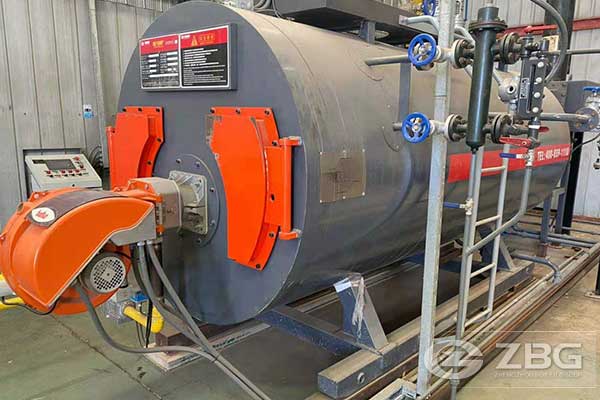
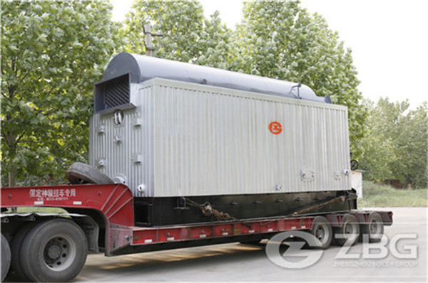
A 50 Tph Coal Fired Boiler With a Pressure of 1.0mpa Supplies Saturated Steam
2022-10-17 08:45:46General
Coal Energy Australia wish to build a coal drying, briquetting and carbonisation plant at the Energy Brix (EBAC) site. The plant will use the existing coal drying and briquetting infrastructure that is at the site but not the old power station boilers and turbines.
An coal fired Boiler will be required to supply up to 50 tph, of saturated steam at 10 barg pressure. The boiler should be capable of steady operation down to 10 tph of steam flow.
A process flow diagram for the Auxiliary Boiler and the associated steam and condensate system is shown in Figure 1.
Figure 1, Process Model of Auxiliary Boiler with Steam and Condensate System. Units: p bara, T °C, m tph.
Fuels
The Auxiliary Boiler will burn waste dry coal produced by the coal drying, briquetting and carbonisation processes. There is also a large stockpile of waste coal (Grus) on-site which can be used in the early stages of the project. This material is of a lower calorific value than the fresh wastes.
The plant is to be capable of operation on coal from any of the three open cuts Yallourn, Morwell or Loy Yang including blends of these coals. The composition of dried coal from these three sources is given in Table 1 below. From a combustion point of view there is little difference between these coal with Yallourn coal having a slightly lower CV. The dried coal burns very easily with little soot formation. Problems can occur with self-heating and subsequent gas and dust explosions in coal bunkers which require the bunkers to be fitted with water/foam fire suppression equipment and hinged explosion relief vents. Bunkers must have steep sided conical sections and avoid any dead zones. Conveyors need to be fitted with heat triggered water spray systems. The explosibility dust constant for Victorian brown coal is 160 Bar.m/s and should be used for explosion vent sizing.
Despite the low ash content of the coals, the ash fouling behaviour of any of these coals can vary from moderate to severe with a strong tendency to form sulphate bonded or sintered deposits on tubes in the convective section and a tendency at times to form sintered ash layers on top of the coal bed in grate fired boilers. Slagging on furnace walls can occur if flame temperatures or heat flux are too high. Due to the fouling tendencies of the coal, all heat transfer surfaces must be frequently (2 to 8 hourly) cleaned by effective sootblowers.
The waste coal (grus and dust) will generally be less than 2 mm particle size and will contain a large amount of fine coal. Coal dust from the coal drying system also needs to be disposed of in the boiler. Typical size distributions of the two waste coal streams are shown in Table 2. The boiler manufacturer is asked to recommend the most appropriate firing system and indicate what experience they have burning fine coal with that system. The boiler needs to include all required coal handling and firing equipment. The coal can be readily pulverised in a hammer mill with a classifier.

Figure 1, Process Model of Auxiliary Boiler with Steam and Condensate System. Units: p bara, T °C, m tph.
Natural gas or LPG will be available for pilot burners for start-up. The boiler should be capable of continuous operation for 50 weeks per year and annual maintenance shutdowns will be for 2 weeks per year
Condensate Return System
The coal dryers operate with a steam pressure of 3.15 barg and the condensate flows by gravity to insulated storage tanks below ground level which are maintained at the same pressure and a temperature of about 135°C. The tanks are fitted with pumps to return the condensate to a boiler feed pump system. The pressurised water does not need to be passed through a deaerator in normal operation.
Makeup water from a town water supply needs to be demineralised by an RO system and passed through a storage tank and a deaerator before being added to the pressurised condensate storage tank. A water softener system alone is not suitable as it will lead to corrosion in the dryers and condensate storage tanks.
The condensate temperature of 135°C creates a problem for the boiler design as it requires the boiler to include an airheater if the fluegas temperature is to be kept below 170°C even with a good economiser included. The air heater can suffer from ash fouling and corrosion and can be expensive. An alternative to the normal airheater is to pre-heat the combustion air using a finned tube heat exchanger that cools the feedwater to about 108°C. This should be smaller and cheaper will not suffer from corrosion or rapid fouling. With this exchanger, the fluegas should be kept below 170°C.
Fabric Filter
The boiler needs to be fitted with a fabric filter (baghouse) to remove the flyash before the ID fan. HRL has found from experience that regular PPS filter bags are not suitable for use with brown coal ash at these temperatures giving a very short bag life. We found that SuperFlex bags (Teflon membrane on fiberglass fabric) are much better.
Stack and Steam Vent
The boiler supply needs to include the chimney stack of a height required to meet local EPA requirements (to be advised).
A DCS controlled steam vent is to be included to allow up to 25 tph of steam to be vented through an effective silencer to the atmosphere to facilitate plant startup and rapid shut down in the event of loss of steam load.
Control and Electrical Equipment
The boiler is to be controlled by a PLC system that will be compatible with the rest of the carbonisation plant and use desktop PCs for the operator interface. Fully automatic operation is required with only one operator present to monitor the operation of all the plant plus another field operator. All operational data is to be automatically logged and backed up. All manuals and PLC tags and alarms are to be in English with SI units.
All boiler systems are to be controlled automatically by the PLC and all operational parameters are to be displayed and logged by the PLC and desktop software. An independent safety shutdown system is required to monitor critical boiler parameters and shut the boiler down if required. The operation of this safety system must be monitored and displayed by a desktop PC.
The boiler power supply will be three-phase at 415 VAC 50 Hz. All electrical equipment and instrument and control systems are to be to Australian standards. All boiler components and systems are to be designed to applicable Australian or ASME standards where these are acceptable. The FD, PA and ID fans are to have VSD for the motors.
Manufacture, Supply and Construction
The boiler shall be constructed outdoors and fully water-proof and dust proof equipment shall be supplied. All hot surfaces are to be insulated and clad with stainless steel water-proof cladding.
The boiler manufacturer must implement a high-quality QA system with monitoring by an independent expert observer. The boiler price should include packaging, shipping and insurance to Melbourne. The cost of engineering assistance with construction and commissioning should be included. Specialist labour from the manufacturer can be considered. It should be noted that there are Government limitations on the extent of overseas labour permissible.
Table 1, Fuel Properties
|
Dried Coal |
|
Yallourn |
Loy Yang |
Morwell |
|
Type: Coal, Dried Brown Coal |
|
|
|
|
|
Fuel supply temperature |
C |
15 |
15 |
15 |
|
Heating Values (at 25C) |
|
|
|
|
|
LHV (moisture and ash included) |
kJ/kg |
21174 |
21883 |
22067 |
|
HHV (moisture and ash included) |
kJ/kg |
22313 |
23021 |
23205 |
|
Ultimate Analysis (weight %) as fired |
|
|
|
|
|
Moisture |
% |
13.50 |
12.50 |
12.50 |
|
Ash |
% |
1.9 |
2.63 |
1.9 |
|
Carbon |
% |
58.0 |
59.06 |
60.4 |
|
Hydrogen |
% |
4.6 |
4.7 |
4.11 |
|
Nitrogen |
% |
0.44 |
0.51 |
0.52 |
|
Chlorine |
% |
0.07 |
0.09 |
0.07 |
|
Sulfur |
% |
0.24 |
0.33 |
0.25 |
|
Oxygen |
% |
21.25 |
20.18 |
20.25 |
|
Total |
% |
100.00 |
100.00 |
100.00 |
|
Proximate Analysis (weight %) |
|
|
|
|
|
Moisture |
% |
13.5 |
12.5 |
12.5 |
|
Ash |
% |
1.9 |
2.6 |
1.9 |
|
Volatile Matter |
% |
43.3 |
40.4 |
44.3 |
|
Fixed Carbon |
% |
41.7 |
44.5 |
42.8 |
|
Total |
% |
100.0 |
100.0 |
100.0 |
|
Other Properties |
|
|
|
|
|
Bulk density |
kg/m^3 |
770 |
770 |
770 |
|
Hardgrove Grindability Index (HGI) |
|
45 |
45 |
45 |
|
Dried Coal |
|
Yallourn |
Loy Yang |
Morwell |
|
Ash Analysis (weight %) |
|
|
|
|
|
SiO2 |
% |
10.0 |
59.9 |
12.0 |
|
Al2O3 |
% |
6.1 |
16.3 |
2.8 |
|
Fe2O3 |
% |
33.9 |
3.5 |
12.4 |
|
CaO |
% |
8.6 |
1.8 |
29.5 |
|
MgO |
% |
19.3 |
4.7 |
21.7 |
|
Na2O |
% |
6.3 |
4.7 |
5.4 |
|
K2O |
% |
0.31 |
0.64 |
0.56 |
|
TiO2 |
% |
0.55 |
0.97 |
0.32 |
|
P2O5 |
% |
0.1 |
0.09 |
0 |
|
SO3 |
% |
15.1 |
7.4 |
15.2 |
|
Other |
% |
0 |
0 |
0 |
|
Total |
% |
100 |
100 |
100 |
|
Ash Characteristics |
|
|
|
|
|
Fouling |
|
Medium to |
Medium to |
Medium to |
|
Ash Initial Deformation Temperature (reducing atm.) |
C |
1150 |
1100 |
1200 |
|
Ash Softening Temperature (reducing atm.) |
C |
1200 |
1150 |
1250 |
Table 2, Equipment List
1.Coal fired boiler, 50 tph, 10 barg, saturated steam, including furnace, steam drums, evaporator section and economiser, coal handling system, firing system, pilot burner system, ash handling system, safety valves and silencers.
2.Sootblower system, compressed air or steam.
3.Fans with VSD: PA, FD and ID fans and all interconnecting ducting.
4.Coal bunker, rising conveyor or equivalent, feeder controller, pulverising system and PF firing system or stoker grate firing system (if suitable).
5.Boiler feed pumps (x 2)
6.Feedwater cooler – air heater to reduce the final fluegas temperature.
7.Makeup water system including filtration plant, RO, storage tank, deaerator and hot condensate pumps, 5 tph capacity.
8.Grit Refiring system.
9.Fabric Filter with ducting and dust disposal system and dust monitor system.
10.Chimney stack with ducting.
11.Steam Vent with silencer, PLC variable control valve.
12.Pressure reduction valve, 10 barg to 3 barg, 0 to30 tph.
13.All required control valves, instrumentation, VSDs, motor control centre, PLCs etc.
14.Structural steel prefabricated.
15.Insulation and stainless-steel cladding of all hot surfaces.
16.PLC based control system with two desktop monitors for operator control and datalogging system. To be compatible with carboniser control system. Independent safety shutdown system.
Table 3 Typical size distributions of waste coal.
The size distribution of the Grus produced in the briquetting plant is shown below. The +2mm fraction will be used as feed to the char kilns, the -2mm material is available as fuel for the auxiliary boiler.
3.1 Fuel 1: Grus typical particle size distribution
|
3.1 Fuel 1: Grus typical particle size distribution |
|
|
Particle Size |
Cumulative Size Distribution |
|
37500 |
96 |
|
25000 |
91.5 |
|
19000 |
87.6 |
|
12500 |
82.5 |
|
4750 |
64 |
|
Boiler Fuel < 2000 µm |
|
|
2000 |
43.6 |
|
1000 |
26.5 |
|
500 |
14.5 |
|
250 |
7.4 |
|
125 |
2.8 |
|
64 |
1 |
|
0 |
0 |
Size distribution of fine dust from briquette factory baghouse.
3.2 Fuel 2: waste dust from briquetting plant
|
3.2 Fuel 2: waste dust from briquetting plant |
|
|
Particle Size |
Cumulative Size Distribution |
|
1002 |
100 |
|
502 |
97.89 |
|
200 |
90.27 |
|
100 |
83.85 |
|
50 |
73.95 |
|
20 |
51.29 |
|
10 |
32.26 |
|
2 |
6.79 |
|
1 |
3.58 |
|
0.4 |
0.13 |
For all inquiries, please fill in the form below (* are required) to send us a brief message, and we will get back to you as soon as possible.
