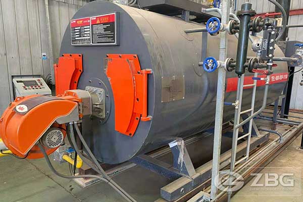
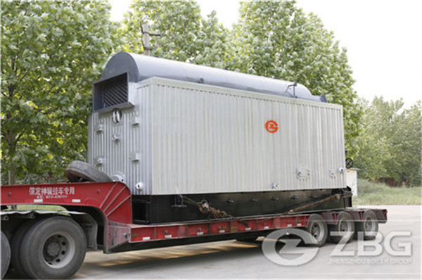
Technical Parameters of 4 Gas Fired Hot Water Boilers
2022-09-12 10:09:44Technical Parameters of 4 Gas Fired Hot Water Boilers
| Pos. | Name of equipment and technical characteristics | Type, brand, document symbol, data sheet symbol | Code of | Supplier | Unit | Quantity | Mass of 1 unit, | Notes |
| Product | kg | |||||||
| 1 | 2 | 3 | 4 | 5 | 6 | 7 | 8 | 9 |
| 1 | Gas Fired Boiler Plant consist of: | set | 4 | |||||
| 1.1 | Gas water heating boiler Q=1500 kW (P=0,6 MPa, t=100 ˚C ) with geyser | UNIMAT UT-L | Вosch | pcs | 1 | 4200 | ||
| 1.2 | Boiler control cabinet | pcs | 1 | |||||
| 1.3 | Pneumatic hydrophore tank Р=0,6 MPa, V=500 L, Т=800С | REFLEX G-500 | 7521006 | pcs | 1 | |||
| 2 | Chemical Water Treatment complete with: | set | 1 | |||||
| 2.1 | Chemical water treatment with chemical deaeration Q=1,0 m3/hr | set | 1 | |||||
| 2.2 | Plastic water storage tank 1,5 m3 | 1500ВФК2 | pcs | 1 | 40 | |||
| 3 | Feed Pump Station complete with: | set | 1 | |||||
| 3.1 | Centrifugal pumps (Т=350С) Q=1,5 m3/hr, | B-NMD 25/190C/A | Calpeda | pcs | 2 | 42,0 | ||
| Н=29 mCE, n=2900 rpm, N=0,51 kW | ||||||||
| 4 | Boiler Circuit complete with: | set | 1 | |||||
| 4.1 | Boiler-circulating pumps (Т = 95 0С) Q=66 m3/hr, | СМ100/1020 | DAB | pcs | 4 | 109,3 | ||
| Н=7 mCE, N=5,5 kW | ||||||||
| 5 | Heat Energy Meter complete with: | |||||||
| 5.1 | Thermal energy flanged tachometer complete with: | SUPERCAL 531 SONTEX 440 AQUATHERM | set | 1 | ||||
| 5.1.1 | Calculator | pcs | 1 | |||||
| 5.1.2 | Flow tachometer DN200, PN10 | pcs | 2 | 77,0 | ||||
| 5.2 | Thermal energy flanged tachometer complete with: | SUPERCAL 531 SONTEX 440 AQUATHERM | set | 2 | ||||
| 5.2.1 | Calculator | pcs | 1 | |||||
| 5.2.2 | Flow tachometer DN65, PN10 | pcs | 2 | 8,7 | ||||
| 5.3 | Thermal energy flanged tachometer complete with: | SUPERCAL 531 SONTEX 440 AQUATHERM | set | 1 | ||||
| 5.3.1 | Calculator | pcs | 1 | |||||
| 5.3.2 | Flow tachometer DN50, PN10 | pcs | 1 | 7,0 | ||||
| 5.3.3 | Flow tachometer DN32, PN10 | pcs | 1 | 4,7 | ||||
| 6 | Hydraulic circuit complete with: | set | 1 | |||||
| 6.1 | Hydraulic arrow DN200, PN10 | 548200 | Caleffi | pcs | 1 | 255,0 | ||
| 6.2 | Magnetic networked sludge trap DN200, PN10, Т=1000С | MOS 400/200 | pcs | 1 | 220,0 | |||
| 7 | Pneumatic tank circuit complete with: | set | 1 | |||||
| 7.1 | Hydraulic hydrophore tank Р=0,6 MPa, V=1500 L, Т=800С | REFLEX G-1500 | 7526605 | pcs | 2 | 297,0 | ||
| 8 | Heat exchangers DHW | |||||||
| 8.1 | S&T Heat exchanger DHW Q=121 kW | Vitocell 100-V CVA 1000 | Viessmann | set | 2 | 367,0 | ||
| 8.2 | S&T Heat exchanger DHW Q=80 kW | Vitocell 100-V CVA 750 | Viessmann | set | 1 | 295,0 | ||
| 9 | Network recirculation unit DHW | |||||||
| 9.1 | Recirculation pump DHW (Т = 60 0С) Q=1,2 m3/hr | |||||||
| Н=6 mCE, N=0,1 kW (carcass – bronze) | IPL 40/70-0.12/2 | Wilo | pcs | 2 | 11,0 | |||
| 11 | Heating circuit system DHW | |||||||
| 11.1 | Centrifugal pump (Т=800С) Q=14m3/hr, Н=5 mCE, N=1,0 kW | IL 65/160-1,1/4 | Wilo | pcs | 2 | 56,0 | ||
| 12 | Network circuit (AHU) | |||||||
| 12.1 | Centrifugal pump (Т=800С) Q=78 m3/hr, Н=15 mCE, N=7,5 kW | IL 100/250-7,5/4 | Wilo | pcs | 3 | 138,0 | ||
| 13 | Network circuit (FCU) | |||||||
| 13.1 | Centrifugal pump (Т=800С) Q=25 m3/hr Н=15 mCE, N=3,0 kW | IL 65/120-3/2 | Wilo | pcs | 2 | 66,0 | ||
| 14 | Network heating circuit | |||||||
| 14.1 | Centrifugal pump (Т=800С) Q=5,5 m3/hr, Н=15 mCE, N=1,0 kW | IPL 32/130-1.1/2 | Wilo | pcs | 2 | 24,0 |
Products Recommended
Success Stories
Checking Order
Quality Test Before Delivery
Check Items When Packing
Packaging And Transport
Get An Instant Quotation
For all inquiries, please fill in the form below (* are required) to send us a brief message, and we will get back to you as soon as possible.
